PowerLabs 200kV Voltage Multiplier! |
 |
|
|
Project Introduction: |
|
The Cockroft-Walton voltage multiplier was
invented in the 30's by two men who gave it their names to serve as
a way of producing very high voltages which would be unpractical to
obtain from transformers due to the bulk of the insulation required.
By using only capacitors and diodes, these voltage multipliers can step
up relatively low voltages to extremely high values, while at the same
time being far lighter and cheaper than transformers. They were, and
still are used in x-ray tubes, particle accelerators, electrostatic
devices, and many other devices making use of very high voltages at
DC values. Needing a high voltage DC source for its electrostatic research, PowerLabs searched all over the Internet trying to find a supplier... Sadly, the few companies out there who make such devices want way too much money for them. So, here's my take on it: |
|
|
Project Description and Goals: |
|
|
|
|
Theory (a simplified overview): |
|
The ripple voltage, in the
case where all stage capacitances (C1 through C(2*n)) may be calculated
from: As you can see from this
equation, the ripple grows quite rapidly as the number of stages increases
(as n squared, in fact). A common modification to the design is to make
the stage capacitances larger at the bottom, with C1 & C2 = nC, C3 &
C4= (n-1)C, and so forth. In this case, the ripple is: For large values of n (>= 5), the n2/2 and n/6 terms in the voltage drop equation become small compared to the 2/3n3. Differentiating the drop equation with respect to the number of stages gives an equation for the optimum number of stages (for the equal valued capacitor design:
Increasing the frequency can dramatically reduce the ripple, and the voltage drop under load, which accounts for the popularity driving a multipler stack with a switching power supply. |
|
|
Construction |
  Here
are a few construction pictures showing the tools and parts used to
assemble the multiplier. The first prototype used three diodes out in
the air; it flashed over almost instantly at around 120kV, destroying
2 legs. Here
are a few construction pictures showing the tools and parts used to
assemble the multiplier. The first prototype used three diodes out in
the air; it flashed over almost instantly at around 120kV, destroying
2 legs.For the second prototype the shape of the diode strings was worked on a bit in order to increase the distance between diodes. That flashed over at around 140kV. The final prototype uses a tight fitting silicone tube around the diodes, and the diodes are coated in oil, both to help prevent flashover and to help them slide on around the tube. This flashed over twice, but it can hold off over 180kV before flashing over. The future plan is to use 4 diode strings for an 80kV holdoff. This should help eliminate the flashovers. Meanwhile I am looking for more capacitors to add more stages to the system. Ideally I would like to run 10 stages for 500,000V DC. I need 12 more capacitors for that, at a cost of around $80 a capacitor. This won't happen any time soon. |
|
|
Results: |

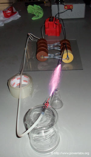
 Here
are some spark pictures showing the best sparks to date, a bit over
7" (before the first stage flashed over). The corona and Ozone smell
are extrmely noticeable, and everything around the output becomes strongly
charged. Here
are some spark pictures showing the best sparks to date, a bit over
7" (before the first stage flashed over). The corona and Ozone smell
are extrmely noticeable, and everything around the output becomes strongly
charged.More pictures to come! |
|
|
Videos: |
| Here are a few videos
of the device in action: This video shows a later test with the cascade being driven to full power and a 7+ inch spark occuring at the output, which is being limited by a water resistor. One of the diodes on the first stage rectifier stack fails, shorting out the entire device. |
|
|
|
Comments? Mail me. Last updated 11/02/10 |
|
Copyright � 2002 -2009 by Sam
Barros. All rights reserved. Removing any material from this site for display without consent from its author consists in an infringement of international copyright laws and can result in fines up to $50000 per infringement, plus legal costs. |

