PowerLabs Rail Gun 2.0 Research!

PowerLabs Rail Gun 2.0 Research! |
|
|
|
|
|
|
|
|
|
|
|
|
Project Introduction: |
 From its conception, the original PowerLabs Linear Magnetic Accelerator
("Rail Gun", or "Railgun") was conceived for
the primary goal of simply proving that it could be done; on a low budget,
with common materials and powered by a never tried before electrolytic
capacitor bank.
From its conception, the original PowerLabs Linear Magnetic Accelerator
("Rail Gun", or "Railgun") was conceived for
the primary goal of simply proving that it could be done; on a low budget,
with common materials and powered by a never tried before electrolytic
capacitor bank.In that, it was extremely successful: Not only did the gun fire flawlessly over 30 times (it is not uncommon for research rail guns to break down in the first shot), but it also attracted vastly more attention than I could ever have hoped for: After its page generated hundreds of thousands of hits, the gun was featured on Discovery Channel, TV6, numerous newspaper and magazine articles, and earned me several job offers from the private sector, research institutes, and industry. The highlight of the popularity of this project came in the form of two separate offers from laboratories associated with the department of defense (DoD), which, apparently can't hire me because I was not born in the USA (someone must have forgotten that the majority of the best scientists and engineers in the world weren't born here)... The original railgun design was completely experimental; built, assembled and operated solely by myself, on my first year of engineering school and being entirely based on my knowledge of electricity and magnetism at the time. With the catastrophic failure of the injector casing and the injector/rail assembly during a full power shot, I found the extra motivation I needed to re-design the gun so that my research in this area could continue. Of course, by now, with 3 years of engineering school and extensive research on the subject, I expected even greater successes. |
|
|
Project Description and Goals: |
| The objective
of this project is to successfully design and construct a linear
electromagnetic accelerator capable of accelerating a lightweight payload
to velocities greater than 1000m/s so that high velocity erosion in
the rail/armature interface can be studied and a means for minimizing
this erosion be investigated. Rail Guns are not by any means a new technology; 50 years ago when the first true rail guns were built and fired it was believed that they would provide a means to accelerate objects to virtually any desired speed, replace conventional weapons and provide cheap orbital launches for small payloads. Today, despite enormous advances in the technology, the maximum muzzle velocities attainable are nowhere near what was once believed possible, and railguns remain confined to the laboratory where some times the rails need to be removed and resurfaced after every shot. The cost of obtaining high acceleration through electrical action between sliding contacts is the rapid destruction of those contacts through arcing and friction. I am not alone in believing that we are very close to a solution to this erosion problem, and it is my belief that once this solution is found it will have profound implications our understanding of materials science, power transmission, high velocity friction, and open new doors to the fields of transportation, defense, manufacturing, and more (321-online-casino.com). As I embark on this research once again to further my knowledge in various fields of science I hope to make a significant contribution to the field of electromagnetic acceleration, which has fascinated me ever since I first learned about it, and hopefully secure a job offer in this field. |
|
|
Theory (a simplified overview): |
 RailGuns differ from other means of accelerating objects in that the
acceleration in the rails occurs purely by magnetic repulsion. This
magnetic force is termed a "Lorentz Force", and it has been shown
to be:
RailGuns differ from other means of accelerating objects in that the
acceleration in the rails occurs purely by magnetic repulsion. This
magnetic force is termed a "Lorentz Force", and it has been shown
to be:Frg = 1/2*dL/dX * I2 [1]. The dL/dX term can also be written as L', the inductance gradient of the rails. From this equation it can thus be seen that even in a well designed Rail Gun (high inductance gradient), the most predominant factor in determining exit velocity will always be the power supply current. Thus it follows that in order to produce high muzzle velocities, long rails and/or very high currents must be used. Unfortunately, maintaining a high current through a long pair of rails requires a lot of energy (Current * Voltage * Time), and with high currents high rates of rail erosion have so far been unavoidable. The exit velocity of a rail gun can be estimated through the equation: V=u+L'/2m * (integral 0→t) I2dt [1] , where u is the injection velocity. Although this equation is of limited use unless the exact shape of the current pulse is known, it once again it demonstrates the importance of a high current. It also states the obvious fact that higher exit velocities will be attainable with higher injection velocities. Not easily seen from the equation, but equally important, is the fact that at higher injection velocities the electrical arcing and ohmic heating between the projectile and the rails will not have as much time to heat the rail surfaces to vaporization. Thus, up to a certain point, a higher injection velocity will help minimize rail damage[10]. It will also prevent rail/projectile spot welding, which can occur at zero injection velocities and low powers on metal/metal contacts. Given the energy expenditure of accelerating the projectile electrically, and the advantages of pre-injection, it makes sense to impart as much initial velocity to the projectile as possible, and only then allow the electric action to do what it is most effective at: attaining velocities that would not be feasible with a gas injection mechanism alone. Resistive losses in a Rail Gun are given by: Wr= R0(integral 0→t)i2dt = 2R0(mv)/L' . With mv being the momentum of the projectile, it can be seen that energy loss in a railgun is proportional to projectile momentum (not kinetic energy, as might be expected), and can be minimized by increasing the induction gradient. This would imply that rail guns are most efficient at accelerating light payloads, which would steer research towards smaller bores; however it has been shown experimentally [9] that with very small calibers (<18mm) the efficiency of a railgun decreases with smaller size bores. Clearly other factors are involved, some of which still unknown. For the sake of simplicity and clarity I will limit myself to these and only a few more equations on this write up. The interested reader is invited to seek further knowledge by reading the sources cited at the bottom of the page (as opposed to creating yet another copy of my design, like so many others seemingly incapable of creative thought and engineering design) |
|
|
|
 The Lorenz force decreases drastically with a reduction in current,
and below a minimum current the accelerating force drops below the projectile
frictional force and thus power is dissipated with no extra kinetic
energy being imparted into the projectile. In order to counter this
loss, the ideal railgun electrical pulse shape is a square wave with
rapidly increasing pulse current, a high plateau, and a fast current
decay. Such a pulse shape can be approximated through a Pulse Forming
Network (PFN).
The Lorenz force decreases drastically with a reduction in current,
and below a minimum current the accelerating force drops below the projectile
frictional force and thus power is dissipated with no extra kinetic
energy being imparted into the projectile. In order to counter this
loss, the ideal railgun electrical pulse shape is a square wave with
rapidly increasing pulse current, a high plateau, and a fast current
decay. Such a pulse shape can be approximated through a Pulse Forming
Network (PFN).As with the previous Rail Gun, this power supply consists of Cornell-Dubilier Inverter Grade capacitors, each rated at 6300uF and 400V (450V Surge). Operating Temperature is -40C to +95C. These capacitors utilize the latest technology in electrolytic capacitor construction to store 640J each in a can measuring only 3" dia. x 5.63" length and weighting 900grams each. Each individual capacitor has a 50KOhm 10W wire wound resistor for charge equalization and also to serve as a bleeder to prevent unwanted charge buildup when power is switched off. They are charged through a 900Ohm current limiting resistor and can be safely discharged through a 6.25kOhm resistor bank mounted inside the bank. In order to counter skin effect related losses the capacitors are inter connected by very large surface area (30in^2) oxygen free copper strips each 0.064" thick (1.6mm). The bank is internally fitted with a Fluke 80K6 6-kV probe for voltage monitoring. The capacitors in the power supply for this railgun has been generously donated by S. Parler of Cornell-Dubilier Electronics. |
|
|
||||||||||||||||||||||||||||||||||||||||||||||||||||||||||||||||||||||||||||||||||||||||||||||||||||||||
Rails and Rail Enclosure Design: |
||||||||||||||||||||||||||||||||||||||||||||||||||||||||||||||||||||||||||||||||||||||||||||||||||||||||
 The magnetic field produced by the rails can be estimated by the Biot-Savart
Law, which calculates the field of a current carrying long straight
wire; B = u0I/2pir. The plot on the right shows how
the magnetic field around a wire rises linearly with current. The wire
in this case has a radius of 0.00635m and its length is dimensionless.
Notice how one Tesla is not achieved until 35000amperes flow through
the wire: Producing a strong field in a straight wire requires vast
amounts of current, and there are several more efficient ways to achieve
these high field strength values without resorting to several tens of
thousands of amperes. Some of these methods are to be explored in another,
future Railgun design.
The magnetic field produced by the rails can be estimated by the Biot-Savart
Law, which calculates the field of a current carrying long straight
wire; B = u0I/2pir. The plot on the right shows how
the magnetic field around a wire rises linearly with current. The wire
in this case has a radius of 0.00635m and its length is dimensionless.
Notice how one Tesla is not achieved until 35000amperes flow through
the wire: Producing a strong field in a straight wire requires vast
amounts of current, and there are several more efficient ways to achieve
these high field strength values without resorting to several tens of
thousands of amperes. Some of these methods are to be explored in another,
future Railgun design.
The final design addressed the weak spot where the injector met the gun itself by eliminating it, making the entire gun a single 24 inch long barrel divided equally between the 12" rails and a 12" channel through which pneumatic acceleration takes place. The rails themselves were milled from a large piece of copper, thus eliminating the need for any welding or brazing.
Below the spot where power is fed into the gun can be seen more clearly. This had to be milled very accurately since that is the point of highest plasma pressure in this particular design.
Material choices on this gun were as follows:
|
||||||||||||||||||||||||||||||||||||||||||||||||||||||||||||||||||||||||||||||||||||||||||||||||||||||||
|
|
||||||||||||||||||||||||||||||||||||||||||||||||||||||||||||||||||||||||||||||||||||||||||||||||||||||||
Injector: |
||||||||||||||||||||||||||||||||||||||||||||||||||||||||||||||||||||||||||||||||||||||||||||||||||||||||
|
I would like to publicly thank Calumet Machine for assisting in the manufacture of the injector gas system; their expertise was critical in choosing and locating the components necessary for the safe realization of this high pressure system. It was a pleasure working with you guys and I am still amazed that you managed to make a paintball tank-steel hydraulic coupler-brass pipe fitting adaptor!
If full power was to be applied to a static armature the rails and whatever was between them would instantaneously melt under the intense localized heat produced by Ohmic heating as 100thousand amperes tried to make it through the contact resistance. In order to prevent the Rail Gun from becoming a spot welder it is necessary that the armature be moving with some initial speed prior to electromagnetic acceleration. Furthermore, there is no point in wasting valuable electrical energy stored in expensive capacitor banks to accelerate the projectile during the first couple hundred meters per second; compressed gas is a far more efficient and economical way of pre-accelerating the projectile until it starts moving at speeds where electrical acceleration makes more sense. Finally, with increasing injection velocities, there is a corresponding decrease in rail erosion, as the projectile spends less time at any given spot on the rails and thus produces less heating and associated material loss.
With this in mind a new injector was designed to provide the highest injection velocity possible. The primary design constraint was the solenoid valve; the highest pressure attainable for a reasonably priced rapid dump high flow solenoid valve was 1200PSI working pressure. As such, the entire injector has been designed around this component. The 1200PSI will place a force just shy of 200pounds on the projectile, accelerating it at at over 20thousand "Gs". Consequently, it will also place a large amount of force on the gun breech, which is why 1/2 thick Aluminum 6061 was chosen as the support material. The mating surfaces were polished to a mirror shine and silicone gasket maker was used throughout in order to ensure everything is gas tight. Ideally this injector should be able to achieve Mach 1 compared to the old design which was only able to push 150m/s at 500PSI.
|
||||||||||||||||||||||||||||||||||||||||||||||||||||||||||||||||||||||||||||||||||||||||||||||||||||||||
|
|
||||||||||||||||||||||||||||||||||||||||||||||||||||||||||||||||||||||||||||||||||||||||||||||||||||||||
Armature Design: |
||||||||||||||||||||||||||||||||||||||||||||||||||||||||||||||||||||||||||||||||||||||||||||||||||||||||
 Perhaps the single most important factor determining Rail Gun efficiency
is the degree of contact between the rails and the armature. Ideally
a perfect electrical contact would exist between the two and cause resistive
losses to be virtually negligible when compared to the rest of the circuit.
These low resistive losses would make for a very low voltage drop across
the rails, which would cause very little resistive heating, zero arcing
and almost no rail erosion. Unfortunately, maintaining perfect electrical
contact between two metallic surfaces that are very small and move at
extremely high speeds relative to one another has so far eluded most
Rail Gun designers. Solid Armature Rail Guns start off as such and quickly
become transitional or hybrid as the metallic contact breaks down and
arcing begins at 1.5km/s+[2] forming a plasma interface. Above 4000m/s
rail guns are almost exclusively of the plasma type [3], but secondary
arcing tends to limit their performance by lowering efficiency as longer
barrels are made [4]. Currently there are 3 approaches to armature design:
Solid armatures employing a V-notched or U-shaped tail, which is forced
against the rails under the high currents present in firing (most common),
brush armatures which utilize hundreds of small metallic wires to maintain
some degree of contact with the rails despite small irregularities (such
as with the French PEGASUS design[]), and plasma armatures, which allow
arcing to occur in a controlled fashion behind the projectile and utilize
that arc to propel a non conductive projectile down the barrel, despite
heavy rail erosion and resistive losses. These were at some point in
time believed to be the only means of obtaining velocities above 5km/s,
although advances in rail and armature design have made it possible
for solid armature designs to perform at similar levels.
Perhaps the single most important factor determining Rail Gun efficiency
is the degree of contact between the rails and the armature. Ideally
a perfect electrical contact would exist between the two and cause resistive
losses to be virtually negligible when compared to the rest of the circuit.
These low resistive losses would make for a very low voltage drop across
the rails, which would cause very little resistive heating, zero arcing
and almost no rail erosion. Unfortunately, maintaining perfect electrical
contact between two metallic surfaces that are very small and move at
extremely high speeds relative to one another has so far eluded most
Rail Gun designers. Solid Armature Rail Guns start off as such and quickly
become transitional or hybrid as the metallic contact breaks down and
arcing begins at 1.5km/s+[2] forming a plasma interface. Above 4000m/s
rail guns are almost exclusively of the plasma type [3], but secondary
arcing tends to limit their performance by lowering efficiency as longer
barrels are made [4]. Currently there are 3 approaches to armature design:
Solid armatures employing a V-notched or U-shaped tail, which is forced
against the rails under the high currents present in firing (most common),
brush armatures which utilize hundreds of small metallic wires to maintain
some degree of contact with the rails despite small irregularities (such
as with the French PEGASUS design[]), and plasma armatures, which allow
arcing to occur in a controlled fashion behind the projectile and utilize
that arc to propel a non conductive projectile down the barrel, despite
heavy rail erosion and resistive losses. These were at some point in
time believed to be the only means of obtaining velocities above 5km/s,
although advances in rail and armature design have made it possible
for solid armature designs to perform at similar levels.In the new PowerLabs design a completely novel armature will be employed which has never before been fired from a rail gun; through advances in materials science a special copper / carbon composite has been made which will retain its dimensional stability due to the extreme heat resistance of carbon, while at the same time not causing excessive resistive losses thanks to a high degree of copper imbedded in it. Other advantages of this material include low residue, the inherent lubricating properties of carbon, ease of machining (can be machined with HSS tools), and the fact that it can never weld itself to the rails. On this photo the compound can be seen being heated with an oxygen acetylene cutting torch. The 5000F flame leaves the carbon virtually unharmed even after several minutes, and copper can be seen evolving from inside the compound, coloring the flame. Much like composite materials have made it possible to construct strong lightweight rail enclosures, different composites should also make it possible to construct a lightweight armature that will withstand the stresses of electromagnetic firing and accelerate payloads with superior performance. Other composites will be tried, as well as conventional armature materials such as aluminum and plasma. The machined rounds weight 4.27grams
Al1100 was also the material of choice for my original railgun. I found, as others did, that when using any solid armature the rail/armature interface must be perfect; should the sliding armature lose contact with the rails for just an instant, it will automatically start an arc which then consumes very large amounts of power and metal. Plasma armatures propelling composite projectiles were planned, but not attempted at this time. |
||||||||||||||||||||||||||||||||||||||||||||||||||||||||||||||||||||||||||||||||||||||||||||||||||||||||
|
|
||||||||||||||||||||||||||||||||||||||||||||||||||||||||||||||||||||||||||||||||||||||||||||||||||||||||
Charger: |
||||||||||||||||||||||||||||||||||||||||||||||||||||||||||||||||||||||||||||||||||||||||||||||||||||||||
|
|
||||||||||||||||||||||||||||||||||||||||||||||||||||||||||||||||||||||||||||||||||||||||||||||||||||||||
|
|
||||||||||||||||||||||||||||||||||||||||||||||||||||||||||||||||||||||||||||||||||||||||||||||||||||||||
Completed Device: |
||||||||||||||||||||||||||||||||||||||||||||||||||||||||||||||||||||||||||||||||||||||||||||||||||||||||
 Here are some shots of the gun right before it was fired for the first time. You will notice a very large inductor next to the barrel; this was necessary to slow the electrical pulse down to a level where the current no longer cratered the rails at the point of initial contact. Feed lines are: Argon Gas (Top right hose into gas injector)
|
||||||||||||||||||||||||||||||||||||||||||||||||||||||||||||||||||||||||||||||||||||||||||||||||||||||||
|
|
||||||||||||||||||||||||||||||||||||||||||||||||||||||||||||||||||||||||||||||||||||||||||||||||||||||||
Results! |
||||||||||||||||||||||||||||||||||||||||||||||||||||||||||||||||||||||||||||||||||||||||||||||||||||||||
|
Railgun 2.0 was originally fired on the summer of 2006 for
a film crew filming an episode of a Discovery Channel show. For those
tests, the Carbon/Copper sintered powder composite was utilized. A further analysis revealed redeposited copper vapor all over the rail channel. It appears as though the carbon/copper composite was too resistive for the particular currents encountered in this gun and localized heating lead the copper within it to vaporize, causing it to fracture from within. It may still prove to be an excellent projectile for rail guns, but only so long as a low current density and limited energy level are adhered to.
Again the chronograph did not work so velocity readings were unavailable. It is not known if the problem relates to muzzle flash, plasma, or EMP. More research is needed in this area. After several shots the gun's efficiency decreased markedly. It was found that the insulator covering the first inch of rails had been blown off and now the armatures were making contact with the first inch of rails, before the power feed. This meant that the Lorenz force was actually slowing the projectile down. Tests were then stopped. More to come!
|
||||||||||||||||||||||||||||||||||||||||||||||||||||||||||||||||||||||||||||||||||||||||||||||||||||||||
|
|
||||||||||||||||||||||||||||||||||||||||||||||||||||||||||||||||||||||||||||||||||||||||||||||||||||||||
Parts List and Construction Pictures: |
||||||||||||||||||||||||||||||||||||||||||||||||||||||||||||||||||||||||||||||||||||||||||||||||||||||||
|
|
||||||||||||||||||||||||||||||||||||||||||||||||||||||||||||||||||||||||||||||||||||||||||||||||||||||||
|
|
||||||||||||||||||||||||||||||||||||||||||||||||||||||||||||||||||||||||||||||||||||||||||||||||||||||||
Works Cited: |
||||||||||||||||||||||||||||||||||||||||||||||||||||||||||||||||||||||||||||||||||||||||||||||||||||||||
| Prior
to the design of this gun the author studied approximately 900 pages
worth of conference proceedings, journals, pHD and Master's Thesis and
technical papers on the subject. Below, for those wishing to pursue
further research in this area, are some of the ones that proved most
useful and are quoted in this page.
|
||||||||||||||||||||||||||||||||||||||||||||||||||||||||||||||||||||||||||||||||||||||||||||||||||||||||
|
|
||||||||||||||||||||||||||||||||||||||||||||||||||||||||||||||||||||||||||||||||||||||||||||||||||||||||
|
Comments? Mail me. Last updated 11/02/10 |
||||||||||||||||||||||||||||||||||||||||||||||||||||||||||||||||||||||||||||||||||||||||||||||||||||||||
|
Copyright � 2002 -2007 by Sam
Barros. All rights reserved. Removing any material from this site for display without consent from its author consists in an infringement of international copyright laws and can result in fines up to $50000 per infringement, plus legal costs. |
||||||||||||||||||||||||||||||||||||||||||||||||||||||||||||||||||||||||||||||||||||||||||||||||||||||||
 The plot on the left illustrates how the magnetic field strength drops
with distance between the rails and increases with decreasing rail width.
Both relationships are exponential. Seeing as the acceleration is a
product of the force created by the magnetic field strength acting on
the mass of the armature, it can be seen that ideally, for the highest
possible field strength a rail gun would have very thin rails, very
close together (not surprisingly, this translates into a large L' value),
running a very high current. Unfortunately these two parameters limit
the mass that can be launched, and also exacerbate the rail erosion
problem, as thinner rails have less surface to dissipate the heat produced
during firing.
The plot on the left illustrates how the magnetic field strength drops
with distance between the rails and increases with decreasing rail width.
Both relationships are exponential. Seeing as the acceleration is a
product of the force created by the magnetic field strength acting on
the mass of the armature, it can be seen that ideally, for the highest
possible field strength a rail gun would have very thin rails, very
close together (not surprisingly, this translates into a large L' value),
running a very high current. Unfortunately these two parameters limit
the mass that can be launched, and also exacerbate the rail erosion
problem, as thinner rails have less surface to dissipate the heat produced
during firing. 


.jpg)
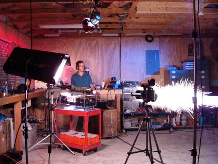 The second round of tests occurred in September 2007, again for Television.
This time aluminum armatures were utilized and these, despite being
deformed by the intense magnetic forces within the gun, held together
and accelerated inside the gun to a high speed.
The second round of tests occurred in September 2007, again for Television.
This time aluminum armatures were utilized and these, despite being
deformed by the intense magnetic forces within the gun, held together
and accelerated inside the gun to a high speed.


