June 05 2004: Rail Gun Disassembled:
 I finally got around to disassembling the gun and examining/photographing
its internals. A lot can be learned from how this design worked, and how
it failed, and this knowledge will be applied on a new, superior design,
which is being designed and built at the moment.
I finally got around to disassembling the gun and examining/photographing
its internals. A lot can be learned from how this design worked, and how
it failed, and this knowledge will be applied on a new, superior design,
which is being designed and built at the moment.
The original PowerLabs Rail Gun was designed in two sections: a
polycarbonate injector with Teflon Rails, and a Rail Gun section with
copper rails and a Garolite G-9 fiberglass composite. The injector was
made from polycarbonate due to its very high tensile strength (10000PSI)
and resistance to shock loads. With the 1/2" thick polycarbonate sheets
holding the Teflon rails under a maximum of 500PSI injection pressure, it
was not believed that this design could fail, thus using polycarbonate
represented a cost saving over the stronger, but much more expensive G-9,
which was used for the rail enclosure where higher forces would be
encountered. In fact, this design was strong enough that it could never
have failed under the calculated load produced by even the highest
possible energies available at the capacitor bank. Failure occurred not
due to Lorenz forces, but rather due to the intense pressure produced when
plasma armatures were repeatedly fired at high energy levels; this higher
pressure was expected, and incorporated into the over design of the gun,
but what was not expected was that the plasma shock actually traveled back
into the injector, and produced enough pressure there to shatter the
material in 5 different places. The breakage of the gun occurred at the
mating point between the polycarbonate and the G-9 materials, indicating
that this connection was clearly the weakest point of the gun. The use of
a weaker material, a two-stage design, and countersunk holes in the
injector bolt holes proved insufficiently strong to withstand repeated
shots at over 10 000Joules. The force of the discharges was enough that,
aside from shattering the Polycarbonate, it bent the steel bolts that held
the injector together, de-laminated the G-9 side supports for the rails,
and deformed the Teflon rail insulators. There is also ample evidence of
plasma blow by past the insulators. This is clearly a source of
inefficiency as the blow by bleeds pressure which would otherwise go
towards accelerating the projectile.
 All
of these design weaknesses have been resolved for the Rail Gun 2.0, which
will be a vastly stronger accelerator, capable of firing reliably and
repeatedly at energy levels of at least twice those seen in this first
design. The rail enclosure will now be a single piece made of Garolite
G-11 (a stronger material than G-9) with no counter sunk holes or mating
points. The rail connector exit points in the gun will also be optimized
to minimize stress concentrations. Another advantage of this re-design is
that rail/injector alignment and rail positioning accuracy will be much
greater. It will also be gas tight, which will provide greater
efficiencies when firing plasma armatures. All
of these design weaknesses have been resolved for the Rail Gun 2.0, which
will be a vastly stronger accelerator, capable of firing reliably and
repeatedly at energy levels of at least twice those seen in this first
design. The rail enclosure will now be a single piece made of Garolite
G-11 (a stronger material than G-9) with no counter sunk holes or mating
points. The rail connector exit points in the gun will also be optimized
to minimize stress concentrations. Another advantage of this re-design is
that rail/injector alignment and rail positioning accuracy will be much
greater. It will also be gas tight, which will provide greater
efficiencies when firing plasma armatures.


The Rails:
The rails held up surprisingly well; after 12 shots without any
kind of servicing they were completely covered in black carbon soot. This
carbon came from the adhesive in the aluminum tape used in the plasma
armatures burning up. It was useful in evidencing the plasma blow by in
the region of initial rail/armature contact.

After cleaning the rails show evidence of cratering and pitting;
classic effects of electrical arc erosion. Significant amounts of copper
have been removed, and a copper/aluminum alloy formed in the bottom of the
craters. Remote Gambling Association The amount of erosion was lower than expected given the number of
shots fired and their energy level (over 150 000Joules were run through
these rails). The insulators were also virtually undamaged by all the
discharge, evidencing that Teflon is a very suitable insulator for this
particular application.

Interestingly, a second arc crater formed 5.6 inches from the
breech. I believe this was due to the armature not making contact with the
rails until that point during a lower voltage shot. That, together with
the extensive arc damage, evidence to the need for closer machining
tolerances and a tighter rail/armature fit, both planned for the next Rail
Gun.

April 7th: Discovery Channel show aired!
|
Lurking in
the electromagnetic lab at Michigan Technical University is a new kind
of super-hero, an undergraduate obsessed with the power of
electromagnetism: PlasmaBoy.

|
 |
March 21: The Rail Gun is on Discovery Channel!
A crew from The Discovery Channel came to my
University to film some of my research on electromagnetic accelerators.
For 10 hours I explained and demonstrated how magnetic fields can be used
to accelerate objects, and how electricity can be stored and converted
into linear motion. The presentations included linear magnetic attraction,
Thompson's coil, the
Coil Gun, and, of course, the Rail Gun.
This should air on "The Daily Planet" some time next month. I'll post the
date as soon as I have the details.
The associate producer for the show insisted that plasma armature shots
were more impressive (I agree). 6 shots were performed with plasma
armatures, at increasingly higher powers. The gun performed flawlessly,
producing some excellent video footage. The last shot, at 14500Joules, was
loud enough to make my ears ring. It also produced enough back pressure to
crack the polycarbonate inductor on 8 different places! The gun will be
repaired soon. As I re-design the barrel to ensure that this can not
re-occur I expect to also make some small upgrades to the gun. The tensile
strength of polycarbonate is 10 000PSI. With only 400PSI on the injector,
my design margin of safety was more than adequate. However it appears as
though the instantaneous localized shock pressures formed when the
aluminum backing on the Teflon projectile turns into a plasma at over 80
000amperes of current must be running in the millions of PSI; sufficient
to blow by the rail insulators and shatter the area around where the
plasma formed. This is very surprising; I expected a lot of pressure, but
not quite this much. It is also very exciting; if the plasma armature is
producing enough force to blow the gun apart, a new design, completely
holding that pressure without deflection should be able to harness it and
convert it into incredible muzzle velocities. Stay tuned, the best is yet
to come!  
 March
17th: I upgraded the Rail Gun charger with a new transformer and a
half wave voltage doubler. Just like the previous one, this assembly came
from a microwave oven. The voltage doubler allows me to charge up the
capacitor bank to a higher voltage, and to do it faster. This is done in
preparation for the Discovery Channel presentation I will be giving this
Sunday. March
17th: I upgraded the Rail Gun charger with a new transformer and a
half wave voltage doubler. Just like the previous one, this assembly came
from a microwave oven. The voltage doubler allows me to charge up the
capacitor bank to a higher voltage, and to do it faster. This is done in
preparation for the Discovery Channel presentation I will be giving this
Sunday.
My first attempt at fast charging caused the current limiting charge
resistor to go up in smoke (that's a 10 inch ceramic resistor!). I was
forced to bypass it. With the current limiting resistor bypassed the
capacitor bank can be charged to 3000V in under a minute! During
charge/discharge tests the charge resistors overheated and melted their
stand. When the resistors fell on top of the capacitor bank they caused an
explosion powerful enough to shear some bolts and lift the top of the box
up. This was very unpleasant. Nothing was damaged and now that the gun is
clean and tested I feel ready for the presentation tomorrow.
 March
16th: I milled a Phenolic block and polycarbonate top to perfectly fit
around the machined rail / inductor connector on the Rail Gun. This block
serves as an insulator for the high voltage connector. With the inductor
now in a permanent mounting position it was time to attempt the first test
firings. These firings are significant in several ways: first of all the
gun now utilizes a much more accurate voltage monitoring system (+- 50V),
which will allow me to make much better calculations relating to
efficiency when I finally get the chronograph to work. Also, the injector
is now operating with Nitrogen. This reduces rail erosion and arcing, and
also, despite the lower pressure (the regulator on the tank will only go
up to 400PSI), should provide a slightly higher muzzle velocity due to
Nitrogen's 30% lower molecular weight. March
16th: I milled a Phenolic block and polycarbonate top to perfectly fit
around the machined rail / inductor connector on the Rail Gun. This block
serves as an insulator for the high voltage connector. With the inductor
now in a permanent mounting position it was time to attempt the first test
firings. These firings are significant in several ways: first of all the
gun now utilizes a much more accurate voltage monitoring system (+- 50V),
which will allow me to make much better calculations relating to
efficiency when I finally get the chronograph to work. Also, the injector
is now operating with Nitrogen. This reduces rail erosion and arcing, and
also, despite the lower pressure (the regulator on the tank will only go
up to 400PSI), should provide a slightly higher muzzle velocity due to
Nitrogen's 30% lower molecular weight.
Finally the addition of the inductor lengthens the duration of the
electrical pulse, lowering current (and thus resistive losses and rail
erosion). Two tests were performed, both with 2300V on the capacitor bank,
amounting to 8300Joules stored energy (less then 50% of what the gun is
capable off; I see no point in burning up the rails with 20KJ before I
actually get the gun working efficiently). The first test utilized an
aluminum foil backed Teflon projectile, and the second one a solid
aluminum projectile. Test videos are available by clicking the respective
test pictures below:
 
The plasma armature shot was of course much louder. The Teflon
projectile destroyed itself on impact unfortunately (those things are a
pain to machine). Both shots produced significant muzzle flash and
trailing sparks, indicating still significant erosion. The aluminum
projectile had metal smeared on it from beginning to end; a big contrast
from the initial non inductor shots which only eroded the very tip of the
projectile; this means that pulse length is now indeed several times
longer with the inductor. I plan on taking an oscilloscope to the gun and
measuring exactly how much longer the pulse length is. The original (non
inductor) test projectiles are show below next to the inductor-fired
projectile for comparison purposes:


 March 8th:
The Rail Gun inductor is now installed! Now all I have to do is mill a
phenolic block to house the custom made copper block connector so as to
insulate it for safety purposes and the gun will be fired in its new
configuration! Stay tuned, big changes are about to happen... Once this
inductor has been used to measure pulse length increase I should be able
to plug the values into my Microsim PSpice circuit simulation and design
an inductor that will bring the pulse length into the 100s of mS, which
will keep the rails under power for several inches of projectile travel
and, if my theory is correct, allow the gun to fire at much higher
efficiencies and velocities. I will also begin some serious work on
getting the Chronograph shielded from the muzzle flash so I can produce
efficiency comparison charts from real muzzle velocity readings. March 8th:
The Rail Gun inductor is now installed! Now all I have to do is mill a
phenolic block to house the custom made copper block connector so as to
insulate it for safety purposes and the gun will be fired in its new
configuration! Stay tuned, big changes are about to happen... Once this
inductor has been used to measure pulse length increase I should be able
to plug the values into my Microsim PSpice circuit simulation and design
an inductor that will bring the pulse length into the 100s of mS, which
will keep the rails under power for several inches of projectile travel
and, if my theory is correct, allow the gun to fire at much higher
efficiencies and velocities. I will also begin some serious work on
getting the Chronograph shielded from the muzzle flash so I can produce
efficiency comparison charts from real muzzle velocity readings.
 February
27th: In order to obtain valuable data from Rail Gun test firings, it
is very important to know the amount of voltage in the capacitor bank. The
original Rail Gun design employed a Simpson 10kV probe in the power
supply, which, divided the voltage by 20; as well as being inaccurate, and
requiring a calculator for reading the values, this probe was also behind
the charge current limiting resistor (400Ohms) and so it read a voltage
that was always greater than the real capacitor bank voltage. Finally, if
the bank was shorted out, the probe would read zero, when in fact there
could be some charge in the bank. All these problems have been taken care
off by the addition of an internally assembled Fluke 80K6 6-kV probe. The
probe provides high accuracy real time /1000 voltage readings for my
multimeter and represents exact capacitor bank voltage across the bank's
end terminals, regardless of what resistance is at the rails. Of course,
this means that the voltage dividing resistor has the full 20000J
available to it, and as such everything is located inside the bullet proof
capacitor bank box. February
27th: In order to obtain valuable data from Rail Gun test firings, it
is very important to know the amount of voltage in the capacitor bank. The
original Rail Gun design employed a Simpson 10kV probe in the power
supply, which, divided the voltage by 20; as well as being inaccurate, and
requiring a calculator for reading the values, this probe was also behind
the charge current limiting resistor (400Ohms) and so it read a voltage
that was always greater than the real capacitor bank voltage. Finally, if
the bank was shorted out, the probe would read zero, when in fact there
could be some charge in the bank. All these problems have been taken care
off by the addition of an internally assembled Fluke 80K6 6-kV probe. The
probe provides high accuracy real time /1000 voltage readings for my
multimeter and represents exact capacitor bank voltage across the bank's
end terminals, regardless of what resistance is at the rails. Of course,
this means that the voltage dividing resistor has the full 20000J
available to it, and as such everything is located inside the bullet proof
capacitor bank box.

 February
20th: I finally got a Nitrogen tank for my lab. The tank is charged to
3000PSI and has a 0-400PSI gas regulator on it. Using Nitrogen Gas for the
Rail Gun projectile injector will increase muzzle velocity (due to the
fact that N2 has a lower molecular weight) and also protect the rails from
oxidation by purging oxygen. February
20th: I finally got a Nitrogen tank for my lab. The tank is charged to
3000PSI and has a 0-400PSI gas regulator on it. Using Nitrogen Gas for the
Rail Gun projectile injector will increase muzzle velocity (due to the
fact that N2 has a lower molecular weight) and also protect the rails from
oxidation by purging oxygen.
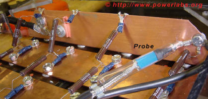
I finished machining the copper connectors for the Rail Gun inductor. The
connectors are solid copper, one bolts on to the capacitor bank inside the
case directly to the end bus bar (thus avoiding exposed HV-carrying parts)
and the second one to the rails through a machined solid copper billet.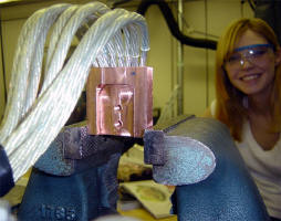 
New Sponsor!: Below is a photograph of 12 neodymium N45 grade supermagnets each 2x2" base
with a 2x1" top and one inch high. These are the strongest magnets I have
ever seen; in one word, they are Dangerous. Strong enough to crush
fingers, drive metal objects through soft wood, or explode on impact when two
are released together. I will be employing their fantastic field strength as
external field augmentation for higher efficiencies in Rail Gun 2.0. They
have been sponsored by Engineered
Concepts; the cheapest and best magnet supplier on the 'net!


February 18th xmicrogamingcasinos.com: The players familiar with online gambling world know that Microgaming creates one the most reliable and popular software out there. A film crew from Discovery Channel is coming here
this Saturday to film the Rail Gun for The Daily Planet and I decided to
upgrade the gun with pulse shaping inductors for the show. I'm somewhat
worried that I'm gambling with too many unknowns so close to a major
presentation but at the same time I am now thoroughly convinced that the
gun does need extra inductance; the pulse length is simply too fast at
63uS; my projectile scorch marks on the rails are under one inch in length
and I can't see any real high efficiency acceleration coming from that
short a travel under power; the smallest research RailGun I've seen to
date was one meter long (granted, it also fired at 200kJ stored) and I'm
assuming it used all 100cm of it to accelerate the projectile to 2km/s.
I'll lose a lot of magnetic force by lowering the current but right now
given current results I am convinced it is worth it. The inductor mounts
are almost complete.
Without an LCR meter, an inductor meter or an oscilloscope I have no idea
what the inductance I am adding to the gun is, but I suspect it is not
nearly enough. Nonetheless, it should start improving results; at 20kJ,
even an improvement of 0.1% in efficiency can make the projectile move
several hundred feet per second faster... That's what I love about working
with big energies :) Can't wait to finish this project and get the 46kJ
capacitor bank out... Can you say "hypervelocity"?!
February 11th: More plasma shots, and new discoveries!

I fired off two more plasma armature shots yesterday; possibly my last
two before the rail gun disassembly for the pulse lengthening inductor and
improvements to the capacitor charge voltage monitoring system.
These shots aimed at testing 3 new ideas/developments and brought about
some new and unexpected discoveries. Below you can see the set up used for
these two shots:


The Rail Gun was set up in the back of the laboratory firing across it
into a trash can full of various materials, from foam to rubber, cloth and
wood. Charging and firing was done remotely from a test stand.


The first test involved a specially shaped projectile: the
triangular tip aims to improve aerodynamics and allow the projectile to
move faster. The back is shaped inwards, with the intent of causing the
propellant pressure to open it up and thus seal it better against the
sides of the barrel. I believe a better seal may prove beneficial in
obtaining higher velocities from the plasma armature, and I know from
observing the first plasma propelled projectile that the plasma armature
is overtaking the projectile (blowby) and causing efficiency losses as it
continues to accelerate on its own.
On this shot's after shot picture (next to projectile picture) it can be
seen that the projectile hit the foam perfectly on its side and cut a neat
impression of it through the foam. The blackening of the sides is from
rubbing against the sides of the rails; the lack of burn marks indicates
that blowby has been reduced. Plasma is still leaking past the top and
bottom of the projectile. This can be reduced by machining a closer
fitting projectile but at some point friction may become too great to and
negate any increase in efficiency from the reduction of blowby. This shot
was not as loud as the first one, and it produced more sparks, indicating
that the aluminum was not completely turned into a plasma. It was however
very fast, penetrating deep into the backstop.

The second test was an attempt at increasing projectile mass; a
sharpened tungsten spear was placed inside a tapered Teflon projectile.
Two layers of aluminum foil were crumpled behind it in order to study the
effect of having a greater mass of aluminum to produce a denser plasma
armature. This shot yielded very surprising results:
The massive muzzle flash and shower of sparks indicates that a lot of
energy was spended in melting and vaporizing the aluminum, and some of it
did not completely turn into a plasma. The shot was *very* loud; the
loudest I have ever heard from this gun. It was also very fast,
penetrating deep into the projectile stop and only stopping when it cut
into one inch of vibration dampening rubber mat. The tungsten spear was
blown out of the hole and into the target, whereupon it disappeared.
Despite the blowby evidenced by scorch marks on the sides of the
projectile, and the pressure leakage from the hole formed when the spear
exited still inside the barrel, this was the fastest shot to date, very
likely to have been supersonic. I believe this was due to the larger mass
of aluminum behind the projectile producing a greater plasma density and
propellant pressure from the vaporization and superheating of the
aluminum. This is counter intuitive as I would expect the energy lost in
vaporizing the aluminum to decrease acceleration efficiency, but
apparently there is a mass of aluminum vs efficiency curve that peaks
somewhere above a single strip behind the projectile. This is very
interesting! I also suspect the ideal mass of aluminum used for a plasma
armature may increase with increased stored energies.
I look forward to firing the gun with pulse shaping inductors very soon,
and attaining unprecedented efficiencies and very high velocities. I
believe the gun has surpassed mach 1, and mach 2 may be within reach at a
full 20 000Joules stored energy.
On the meantime I apologize for the lack of chronograph readings (which,
of course, are the only truly meaningful of accessing real efficiencies)
and invite you to enjoy the following video, showing the test firing of a
conventional (metal) armature projectile and all my 3 plasma armature
shots to date, for comparison purposes. The last shot is the one using the
extra aluminum foil backing, notice how much louder it
sounds. Click on slideshow for video.

February 6th: Rail Gun Plasma shot!

Click on the picture to download video. The video is approximately
50 seconds long, 10MB. It shows me bypassing the safety fuse on my power
supply, charging the Rail Gun air tank to 450PSI, and loading an aluminum
backed Teflon slug into the barrel. The first shot is aimed at an apple.
It fails in that the aluminum backing does not form an electrical
connection with the barrel and thus the projectile "only" reaches +-
600fps from air alone before blasting the apple to pieces against the
backstop. The second shot is performed at a much lower 100PSI and with a
starting velocity of around 70m/s the projectile is now further
accelerated by a plasma armature, leaving the barrel with the sound of a
rifle shot and proceeding to perforate the backstop and embed itself into
a catalogue. The muzzle blast is a lot cleaner, with no sparks and nothing
but a concentrated 5 - 6 feet long purple plasma "flame" leaving the
barrel. The gun is also (not too surprisingly considering the extremely
high temperatures and resulting pressures of a multi megawatt plasma)
much louder with the plasma armature. Still no chrono readings but I
am now thoroughly convinced that a pulse shaping inductor is in order.
Details for the shot: 100PSI, 2.2KV.
More video to follow. Comments are always welcome.

This is the projectile after being fired with an aluminum
armature. Notice the massive amounts of plasma blow by which scorched it
and left it with black marks on all sides. This plasma blow by is an
efficiency loss that must be corrected.
January 30th: Pictures of my new laboratory:

I think I've figured out how to mount the inductor. I will use an
internal connection and a lathe made (by myself of course) massive copper
plug/jack assembly. Machining begins tomorrow.
 January
22nd: I am back from my co-op as a Systems Engineer at Vermont Yankee
Nuclear Power station, and there have been many changes to the Rail Gun
project. First of all the Advanced Space Propulsion laboratory where I was
currently working received a new vacuum chamber, which now takes up all
the available space. My research has thus been moved to the Sub Basement
of the Mechanical Engineering building at Michigan Technological
University, at the Internal Combustion Engine and Dynamics Research
Laboratory. It is a much larger lab, where I have my own desk, table and
storage space. On January 20th the gun was moved to its new location and
set up, and on January 21st it was fired for filmed presentation for TV6,
a local news station. It performed well. I'll upload the video when I get
it. Gambling Commission January
22nd: I am back from my co-op as a Systems Engineer at Vermont Yankee
Nuclear Power station, and there have been many changes to the Rail Gun
project. First of all the Advanced Space Propulsion laboratory where I was
currently working received a new vacuum chamber, which now takes up all
the available space. My research has thus been moved to the Sub Basement
of the Mechanical Engineering building at Michigan Technological
University, at the Internal Combustion Engine and Dynamics Research
Laboratory. It is a much larger lab, where I have my own desk, table and
storage space. On January 20th the gun was moved to its new location and
set up, and on January 21st it was fired for filmed presentation for TV6,
a local news station. It performed well. I'll upload the video when I get
it. Gambling Commission
 Work must now progress quicker, as the gun will soon be featured on
Discovery Channel.
Work must now progress quicker, as the gun will soon be featured on
Discovery Channel.
As such I have decided to tackle the first problem and largest
inefficiency cause in the gun: the pulse length is extremely short (63uS)
and causes all of the energy to be dissipated in a very small segment of
the rails: some times as little as 1 inch! With such a fast, there are two
problems: Power amounts to the energy in the capacitor divided by the
discharge time. With the current pulse length of 63uS a full 20kJ charge
will dump nearly 330MW, or 90 thousand amperes on the rails. Resistive
losses are a product of the square of the current, so even the relatively
small rail and (particularly) arc contact resistance of the gun there is a
LOT of energy being lost. This loss manifests itself as low efficiency and
a dramatic erosion to the rails. Also, with such a short pulse, the
magnetic field formed behind the projectile is non optimal. By lengthening
the pulse, acceleration will occur for a longer period of time, rail
damage will be spread out over a larger area, and resistive losses will
decrease. The accelerating force may be lower, but I theorize that this is
the way to go for higher efficiencies.
So how to increase the pulse length?
 With an inductor of course. This picture shows my first
two prototypes: A toroidal air-cored (non-saturable) inductor with 23 turns of
insulated AWG 4 oxygen free copper wire around a 2.35 diameter PVC pipe
loop. The loop outer diameter is 8" on average. Anyone who has taken apart
a power supply will recognize this as a super size version of a very
common component in DC power supplies :) The second one utilizes the exat
same amount of wire and turns but is a linear arrangement. The inductor will be added in
series with the rails and slow down the pulse. A detailed analysis of this
will come soon. A second inductor is also being built so series vs.
parallel arrangements can be tried. I suspect eventually the gun will be
using a lot more inductance than this. But its a start... Figuring out how
to connect it to the gun will be a challenge of its own... With an inductor of course. This picture shows my first
two prototypes: A toroidal air-cored (non-saturable) inductor with 23 turns of
insulated AWG 4 oxygen free copper wire around a 2.35 diameter PVC pipe
loop. The loop outer diameter is 8" on average. Anyone who has taken apart
a power supply will recognize this as a super size version of a very
common component in DC power supplies :) The second one utilizes the exat
same amount of wire and turns but is a linear arrangement. The inductor will be added in
series with the rails and slow down the pulse. A detailed analysis of this
will come soon. A second inductor is also being built so series vs.
parallel arrangements can be tried. I suspect eventually the gun will be
using a lot more inductance than this. But its a start... Figuring out how
to connect it to the gun will be a challenge of its own...
June 17th: Today was my safety review day; had my
advisor and a pulsed power professor from the EE department look over all
my schematics and gun wiring and make some suggestions before I begin
firing the gun in the University. The required modifications are as
follows:
1- Replace steel Rail Gun mounting bolts for Nylon ones.
2- Place safety cover on discharge switch.
3- Ground Rail Gun barrel bolts or replace them for fiberglass reinforced
nylon ones.
4- Make projectile backstop (must be able to stop a rifle round).
Looks like I'll be busy... The gun might also be moved to another
laboratory on the 5th floor of the Mechanical Engineering building... No
more powered testing for another couple of weeks. On my side, my current
plans for the gun are to build a muzzle flash suppressor so I can use it
with a light break chronograph, to test fire it with a plasma armature and
to obtain oscilloscope traces of the gun firing with metal and plasma
armatures. With the data from those shots I will begin work on an inductor
and then possibly a power switch.

June 16th: After a series of tests with the rail gun
injector I obtained a more accurate plot of the velocity imparted to the
projectile at 6 feet from the muzzle versus the pressure present on the
injector air tanks at the time of firing. It is very interesting to note
that the curve follows what appears to be a logarithmic plot; I.E.
doubling the pressure in the air tank will quadruple the amount of energy
stored in it and make a lot more noise during firing but will not at the
same time double the injection velocity; it appears as though after a
certain point increasing the pressure substantially will not result in
very substantial velocity increase. Currently the injector is firing at
150m/s, with a variation of +- 2m/s between shots. This injector is also
able to fire a Teflon projectile at 195m/s (634.5fps, 696km/h, 432.6mph). It is important to note that
when power is applied to the projectile it is only halfway through the
rails and therefore not traveling as fast as the ultimate injection
velocity, but these will be the values used for calculating the gun
efficiency. I plan on making a chart of injector pressure vs. kinetic
energy to see if that is more linear. Current kinetic energy for the gun
is 67.5Joules prior to injection. This is quite insignificant when
compared to the 20 000 that is being applied electrically to the
projectile during firing.
June 13th: Thyrathon switched Rail Gun? Maybe not: this is
what
L-3 electron devices had to say about my idea:
"Sam,
Our thyratron engineer looked at your requirements and suggested a spark
gap. It was beyond the capability of the thyratrons that we currently
manufacture.
Buzz Miklos"
A spark gap, huh? Considering how loud the one on my Tesla
Coil was while switching .5joules, I think I will pass on a 360 megawatt
spark. Looks like I will just have to build my own thyrathon... I
practiced some oxyacetylene metal cutting today. Next week I will work
some more on the muzzle flash suppressor and on some gun documentation for
the safety review on Tuesday.
 June
12th: Finished wiring the power supply, installed the air tank,
hydrostatically tested it to 600PSI. It appears as though the extra
pressure is not all that beneficial to muzzle velocity: the gun right now
is clocking around 500fps with 500PSI in the tank. June
12th: Finished wiring the power supply, installed the air tank,
hydrostatically tested it to 600PSI. It appears as though the extra
pressure is not all that beneficial to muzzle velocity: the gun right now
is clocking around 500fps with 500PSI in the tank.
Today was the big day! After testing all systems the Rail Gun capacitor
bank was charged to 1700V, which yields an energy stored of just under 9kJ
and the gun was fired into a very heavy catalogue. I suspected that the
muzzle flash would "blind" the very sensitive light break chronograph and
attempted using three sheets of corrugated cardboard as a makeshift muzzle
flash suppressor. It did not work well enough that the chronograph gave me
a reading (it just said "error", as it does when a picture is taken inside
the room) but the shot was nonetheless spectacular. It was about as loud
as firing a gun inside the room (from now on earmuffs a must!), the air
filled with an acrid ozone smell, computer monitors flickered and the
projectile had enough energy to punch into 700 pages of the 1500+ page
catalogue. With air alone at 500PSI the projectile barely sticks to the
paper. It is not possible yet to determine if the projectile is going
supersonic or not but the gun is definitely imparting a substantial amount
of kinetic energy to the projectile!
Below are some pictures of the setup and the damage caused by the shot.
The video is available for download at the bottom.


A quick note about Rail Guns: The muzzle flash that occurs when the
gun is fired is unavoidable and a direct byproduct of their operating
method (sliding electrical contact). The flash and sparks are seen every
time the gun is fired and although they represent a power loss, they are
an unavoidable one. I find it somewhat sad that certain jealous
individuals need to repeat over and over again on a message board that my
rail gun shoots sparks as though that was some kind of defect.
And at last, what you were all looking for:
The Rail Gun >9KJ Test Fire Video!;
air at 500PSI and >9000J on the capacitor bank. BTW for comparison purposes
the injector is imparting approximately 80J of kinetic energy into the
projectile right now. I will need a better camera than my Sony digital
camera to capture more frames of the muzzle flash but this gives a good
idea of what the firing looked like live. Look forward to more powered
testing as soon as I build a more effective way to shield the chronograph!
 June
11th: Finished wiring and building the temporary high voltage
power supply. It is pretty crude, made from wood an without too much
engineering behind it but as the name implies it, all I want it for are
some preliminary tests. I got around the safety concern of using wood by
having all the connections inside the power supply being made from high
voltage rated wire. The PSU is grounded and a 1:20 high voltage probe is
being used to monitor charge voltage. I charged up the Rail Gun today to
2000Volts (about 7KJ) and discharged it through its discharge resistors.
Everything is working well but I might in the future reduce the size of
the discharge resistors and the charge resistor so as to make everything
charge/discharge faster. June
11th: Finished wiring and building the temporary high voltage
power supply. It is pretty crude, made from wood an without too much
engineering behind it but as the name implies it, all I want it for are
some preliminary tests. I got around the safety concern of using wood by
having all the connections inside the power supply being made from high
voltage rated wire. The PSU is grounded and a 1:20 high voltage probe is
being used to monitor charge voltage. I charged up the Rail Gun today to
2000Volts (about 7KJ) and discharged it through its discharge resistors.
Everything is working well but I might in the future reduce the size of
the discharge resistors and the charge resistor so as to make everything
charge/discharge faster.
I also got around to painting the new injector and the temporary
power supply box. Glossy black enamel of course; my favorite color for
weaponry :)
 June 10th: Threaded the 1/2" brass valve connection in
place, glued it with 6 hour metal epoxy and filled the CNC machined 1/2"
polycarbonate valve connection piece with two part epoxy for added
strength, finished gluing everything. Tomorrow the tank will be painted
and the old one will be removed. Hydrostatic testing will hopefully take
place on Thursday, with test firing possibly occurring the same day. June 10th: Threaded the 1/2" brass valve connection in
place, glued it with 6 hour metal epoxy and filled the CNC machined 1/2"
polycarbonate valve connection piece with two part epoxy for added
strength, finished gluing everything. Tomorrow the tank will be painted
and the old one will be removed. Hydrostatic testing will hopefully take
place on Thursday, with test firing possibly occurring the same day.
While I waited for the glue to dry I worked some more on the
Power Labs High Efficiency Coil Gun prototype.
June 9th: Glued the PVC elbows, end caps, pipe and tee
together and screwed the brass elbows and brass tee together with teflon
tape. I drilled and tapped a hole on one of the end caps for the brass
filling system to go into and filled the cap up to 1/4 inch depth (6mm)
with metal epoxy so as to strengthen the plastic pipe that had been
weakened by the threading. I also CNC milled a precision flat end cap for
the middle of the tee where I will thread the valve attachment. Tomorrow
hopefully I will paint the completed air tank and it will be ready for
hydrostatic testing on Wednesday. I will probably hydrostatically test it
all the way to 650 or even 700PSI due to the extremely dangerous nature of
the high pressures that this tank will hold.
June 7th: The parts for the new 500PSI Rail Gun injector
arrived today. The new ball valve and pressure gage attachment will allow
me to charge the gun up with air at a very accurate pressure and close off
the tank, which would make it possible to take the charged injector to a
remote place where testing could be performed without a source of air. The
1 1/4 SCH 80 PVC looks very strong, and I would most definitely feel safer
around it at 500PSI than I did around the 1 1/2 SCH 40PVC at 300.
Lets just hope the 300 PSI solenoid valve feels the same way I do.

 June
05: I spent most of my day practicing some MIG welding for the
Junkyard Wars show I'm going to be in on 37 days, but I still found some
time to test the temporary Rail Gun charger and build more of the box that
will house it. I also got a high voltage test probe from one of the
electricians here, so as far as parts go I'm all set! I charged the gun up
to 200V today and everything works beautifully. June
05: I spent most of my day practicing some MIG welding for the
Junkyard Wars show I'm going to be in on 37 days, but I still found some
time to test the temporary Rail Gun charger and build more of the box that
will house it. I also got a high voltage test probe from one of the
electricians here, so as far as parts go I'm all set! I charged the gun up
to 200V today and everything works beautifully.
June 04: Non metals centre still closed (they are
re-varnishing the tables there and so no dust can go into the room). I cut
a polycarbonate square for the rectifier bridge, helped a friend clean his
motorcycle engine and built an entire coil gun so as to have something to
do for the afternoon. The new coil gun will have its own dedicated page
some time soon; stay tuned.
I made a chart relating the rail gun injector muzzle velocity with the air
pressure present on the air tank at the moment it was fired. This data is
preliminary as the pressure measurements were read off the regulator and
since it has a 4000PSI scale it is difficult to read accurately at such
low values. We can see that the relationship is somewhat linear, but that
after 200PSI further increases in pressure do not seem to be causing equal
increases in velocity (or perhaps the projectile became damaged after the
3rd test).
A more accurate chart will be created once the new injector is ready.

June 03: The non metals centre was closed so I could not
work on the charging power supply box. I gave the projectile injection
issue some more thought and decided that the current injection velocity
would require a very significant amount of inductance to be placed on the
circuit, which will produce a lot of undesirable oscillations and thus
make it very difficult for a solid state switch to be implemented into the
circuit in the near future. In order to lower the induction requirement I
quickly designed a new, intermediate pressure injector by designing an air
tank made from 1 1/4 inch SCH 80 PVC as opposed to the current 1 1/2 SCH
40 PVC. This changes the working pressure of the air tank from 330PSI to
520PSI, although it will involve over loading the solenoid valve a certain
amount. The gun injector should be operating at 500PSI
and having accurate pressure monitoring built into it starting next week.
Below is a list of the materials that will be used for the conversion.
Doubling the air pressure inside a tank quadruples the energy stored,
therefore the new injector should be firing with perhaps 60% higher
velocity, maybe more when Nitrogen is used. I am still working on the
final design, for the second Rail Gun to be built which will employ
3000PSI valves and should achieve supersonic velocities.
|
Quantity |
Description |
Unit
Price |
Ext.
Price |
Ships |
|
1 EA
|
Dual Scale
Steel-Case Gauge 2% Mid-Accuracy 2" Dial, 1/4" NPT Bottom, 0-600 Psi |
$7.24
EA |
$7.24 |
today |
|
2 EA
|
Brass Threaded
Precision Pipe Fitting 1/4" Pipe Size, 90 Degree Male Elbow, 4100 Psi |
$7.09
EA |
$14.18 |
today |
|
1 EA
|
Brass Threaded
Precision Pipe Fitting 1/4" Pipe Size, Tee, 3000 Psi |
$6.41
EA |
$6.41 |
today |
|
1 EA
|
Extruded Brass
Threaded Pipe Fitting 1/2" Pipe Size, Fully Threaded Nipple, 1-1/8"
Length |
$1.52
EA |
$1.52 |
today |
|
1 EA
|
Dark Gray PVC
Schedule 80 Unthreaded Pipe 1-1/4" Pipe Size X 5' Length |
$4.49
EA |
$4.49 |
today |
|
2 EA
|
PVC Sch 80
Unthreaded Pipe Fitting-Dark Gray 1-1/4" Pipe, 90 Deg Elbow |
$2.60
EA |
$5.20 |
today |
|
1 EA
|
PVC Sch 80
Unthreaded Pipe Fitting-Dark Gray 1-1/4" X 1" X 1-1/4" Pipe, Reducing
Tee |
$5.16
EA |
$5.16 |
today |
|
2 EA
|
PVC Sch 80
Unthreaded Pipe Fitting-Dark Gray 1-1/4" Pipe, Round Cap |
$3.78
EA |
$7.56 |
today |
|
1 EA
|
Plastic-Pipe
Cement PVC Heavy Duty, 8 Ounce Dauber-Top Can, Clear |
$2.93
EA |
$2.93 |
today |
|
1 EA
|
Chrome-Plated
Brass Ball Valve W/Lever Handle 1/4" NPT Female Connections |
$4.03
EA |
$4.03 |
today |
|
1 EA
|
Extruded Brass
Hex Nipple 1/2" Pipe Size, 1-13/16" Length |
$2.03
EA |
$2.03 |
today |
|
1 EA
|
Extruded Brass
Threaded Pipe Fitting 1/2" Pipe Size, Fully Threaded Nipple, 1-1/8"
Length |
$1.52
EA |
$1.52 |
today |
|
1 EA
|
Extruded Brass
Threaded Pipe Fitting 1/4" Pipe Size, Fully Threaded Nipple, 7/8"
Length |
$0.49
EA |
$0.49 |
today |
|
Total: |
$62.76 |
 June
02: 7 hours of work today. The day started off bad when, after
building a full wave bridge rectifier for the high voltage charging supply
my volt meter caught fire during a low voltage measurement (cheap radio
shack piece of ...). I did get a current measurement though, but it was
off scale for the meter (>500mA). After dinner my allied electronic order
for HV connectors had arrived, as had my shooting chronograph, and so I
decided to go back to the Advanced Space Propulsion lab and do some more
work. I removed the old coaxial power connectors from the capacitor bank,
re-drilled the connector feed through hole, along with 8 more bolt holes
for securing the new connectors, bolted down the two new MHV 5kV
connectors in place and wired everything back up, including the last 8
bleeder resistors and the capacitor bank end terminals. I ended up
crimping the bleeders on to the end terminals so next time the gun is open
I will do a more professional job and drill holes at the capacitor bank
end bars so they can be bolted on, but for now THE GUN IS COMPLETE AND
READY TO FIRE! As soon as the capacitor bank charging supply is built
testing will resume. June
02: 7 hours of work today. The day started off bad when, after
building a full wave bridge rectifier for the high voltage charging supply
my volt meter caught fire during a low voltage measurement (cheap radio
shack piece of ...). I did get a current measurement though, but it was
off scale for the meter (>500mA). After dinner my allied electronic order
for HV connectors had arrived, as had my shooting chronograph, and so I
decided to go back to the Advanced Space Propulsion lab and do some more
work. I removed the old coaxial power connectors from the capacitor bank,
re-drilled the connector feed through hole, along with 8 more bolt holes
for securing the new connectors, bolted down the two new MHV 5kV
connectors in place and wired everything back up, including the last 8
bleeder resistors and the capacitor bank end terminals. I ended up
crimping the bleeders on to the end terminals so next time the gun is open
I will do a more professional job and drill holes at the capacitor bank
end bars so they can be bolted on, but for now THE GUN IS COMPLETE AND
READY TO FIRE! As soon as the capacitor bank charging supply is built
testing will resume.

With the gun ready and more powered tests imminent, it was
time to start getting some muzzle velocity measurements. I set up a gun
chronograph 6 feet away from the gun barrel with multiple cardboard sheets
and wood as a backstop and fired several rounds through the chronograph.
At 300PSI, the gun consistently fires a 1x1x.25" (25x25x6mm) 6 gram
aluminum slug at over 450feet per second (137m/s), with a top muzzle
velocity of 482.5fps (147m/s, 529km/h, 329mph). This amounts to 64J
kinetic energy, although on these tests the entire 2 feet length of the
injector + rails is providing acceleration: on a powered test after 13
inches the electricity starts to provide more acceleration, and so the
actual projectile injection velocity is a value significantly lower than
the ones quoted here. The primary function of the injector is to simply get the
projectile moving so that it does not weld in place inside the rail gun
barrel, and as such any moderate velocity should suffice. However, even at
147m/s with the measured 63.4uS pulse length the projectile will move only
9mm under power if we assume no electrical acceleration. I find it
unlikely that this gun is going to work with a metal armature until I
design and implement a pulse lengthening inductor into the circuit, but
before this happens I first plan on obtaining data for muzzle velocities
with metal armatures and, more importantly, plasma armatures.
Click on the shooting setup picture below to view a Rail Gun muzzle
velocity measurement video (the video is somewhat dark because the
chronograph can not be used under fluorescent lighting).

I am also currently designing a new injector for the gun.
Given the one foot (30cm) barrel length limitation on this gun it seems
likely that the new injector will run at very high pressures, possibly
1000PSI - 3000PSI. Ideally, the goal would be to inject the projectile at
supersonic velocities and increase its velocity further by another mach
number or two.
May 30th: Ordered new high voltage connectors (MHV
Military grade 5kV connectors, $22.50 a pair) for the capacitor bank and a
Chrony F1 gun chronograph, 30 - 7000fps range 99.5% accuracy, so that I
can start gathering some hard data on muzzle velocities and efficiencies.
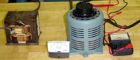
Today I officially begun work on the power supply, buying a panel ammeter
and an analogue voltmeter. I put the variac and transformer together and
obtained some voltage measurements from the combo. The transformer is a
1:20 current limited (shunted) step up transformer and put out 1000V at
50V input from the variac. Monday I hope to assemble a full wave bridge
rectifier for it and start work on a power supply box. I still need a
voltage divider so that I can measure the actual capacitor bank voltage as
it charges up, all the way to 3600 Volts, but my advisor may be able to
help me with that.
February 5th: 4 hours of work: Fine tuned the rail
spacing on the gun, milled some Teflon ammunition for it and did some
tests with the new ammo. Teflon shoots FAST! Low weight and a low
coefficient of friction should allow it to be injected at near supersonic
velocities.
February 3rd: 3hours of work:
Polished the rails ,
first with 400grit sandpaper, then with Brasso, a mildly abrasive ammonia
based metal cleaning product. Looks pretty good; I could have made it
better but I don't think it will matter too much after the first couple of
shots turn the mirror like finish of the rails into a mixture of metal
oxides, blasted holes and molten metal droplets... The gun is now once
again re-assembled, but I still need to adjust the exact spacing on the
rail insulators since the rails are now exactly 1/100th of an inch
thinner. ,
first with 400grit sandpaper, then with Brasso, a mildly abrasive ammonia
based metal cleaning product. Looks pretty good; I could have made it
better but I don't think it will matter too much after the first couple of
shots turn the mirror like finish of the rails into a mixture of metal
oxides, blasted holes and molten metal droplets... The gun is now once
again re-assembled, but I still need to adjust the exact spacing on the
rail insulators since the rails are now exactly 1/100th of an inch
thinner.
 I also finally got around to installing the bleeder / charge equalizing
resistors; Each one of the 40 resistors had to have its terminals
individually bent and than have a terminal crimped in place on it (80
terminals). Than I had to disassemble the capacitor bank, unbolt all the
capacitor terminals (64 in total) and re-bolt them with the resistors in
place. I got 4 blisters on my hand from doing that. Still have 8 bleeder
resistors to go: these will go across the last row of capacitors when I
install the end terminals. Right now the capacitor bank will have to
remain open though because my advisor will not allow me to use coax
connectors on the bank and therefore I have to find a supplier for High
Voltage connectors and have those fitted on the capacitor bank. Finding
High Voltage (4kV 1A) connectors is proving to be far more of a challenge
than I originally expected.
I also finally got around to installing the bleeder / charge equalizing
resistors; Each one of the 40 resistors had to have its terminals
individually bent and than have a terminal crimped in place on it (80
terminals). Than I had to disassemble the capacitor bank, unbolt all the
capacitor terminals (64 in total) and re-bolt them with the resistors in
place. I got 4 blisters on my hand from doing that. Still have 8 bleeder
resistors to go: these will go across the last row of capacitors when I
install the end terminals. Right now the capacitor bank will have to
remain open though because my advisor will not allow me to use coax
connectors on the bank and therefore I have to find a supplier for High
Voltage connectors and have those fitted on the capacitor bank. Finding
High Voltage (4kV 1A) connectors is proving to be far more of a challenge
than I originally expected.
Until I get the high voltage connectors I plan on working on the
capacitor bank charging supply.
January 26th:
4 hours of machine shop work today; I replaced all the SS bolts on the
capacitor bank top for Nylon bolts and milled off 1/100th of an inch from
the rail surfaces so as to remove the damage caused by the previous 2
shots. I still need to install the charge equalizing/bleeder resistors and
replace the charging high voltage connectors (as per my advisor's
recommendations) and the gun will then finally be ready for testing in the
University labs!
  12/21/02:
I finally obtained a high voltage charging supply for the Rail Gun
Capacitor bank: The charger consists in a Samsung Inverter Tecnology
Microwave Oven Power Supply: 1.5kW continuous, 4kV adjustable. I also
bought 20 1inch^2 1/2inch thick grade N38 Neodymium Supermagnets. These
are STRONG! The kind of magnets that will explode into pices with the
impact of letting two come together. They will be employed on my second
Rail Gun prototype as soon as testing is complete with the first
prototype. 12/21/02:
I finally obtained a high voltage charging supply for the Rail Gun
Capacitor bank: The charger consists in a Samsung Inverter Tecnology
Microwave Oven Power Supply: 1.5kW continuous, 4kV adjustable. I also
bought 20 1inch^2 1/2inch thick grade N38 Neodymium Supermagnets. These
are STRONG! The kind of magnets that will explode into pices with the
impact of letting two come together. They will be employed on my second
Rail Gun prototype as soon as testing is complete with the first
prototype.
11/17/02: The bleeder
/ charge equalizing resistors have arrived ($140, from allied
electronics). They are rated at 10W, 50kOhms, 5% tolerance, wire wound.
Now I have to sort out the 32 best ones from the pack of 50 (best meaning
closest to the value of 50k), solder end terminals to all of them, connect
one across each individual capacitor in the bank, re-drill and re-tap the
holes on the capacitor bank top for Nylon bolts, and re-assemble the gun.
Work resumes Monday.
11/01/02: In order to
fire the gun in the University some safety features are required by the
building safety committee; namely high voltage rated connectors and
bleeders. At the moment I am still waiting for the bleeder resistors so I
can resume testing at the University. I will also be presenting it for
some University Physics classes. Since I don't have any machine shop work
to do until the resistors arrive I have been working on some mathematical
models for the gun. On the Rail Gun page you
will find the PSpice schematic I am using to simulate the gun. It
incorporates measured values for capacitor ESL and Capacitance as well as
calculated values for Rail and circuit resistance. I hope to have some
simulation snapshots up soon.
Also, due to the overwhelming demand for it I decided to make the
Rail Gun 15kJ Test Shot Video available.
I was hoping someone would e-mail me one of the better videos taken at the
presentation since the only video I had (where the snapshots came from)
was captured from an analogue camera using my notebook TV Tuner Card,
meaning that it is both low quality and doesn't have any sound. I put the
sound of the 300 PSI shot over the video so its not all silent. Until I
get some better video I guess this is all I'll have available.

 10/21/02:
Got around to opening up the gun today...Very interesting! As expected the
rails erosion took place on a similar length to that at which the
projectile was damaged. This further confirms my hypothesis that the pulse
was short enough that the projectile didn't even get to be fully injected
into the rails before all the energy was gone. I was however very
satisfied at how well the spacers and the rail insulators took the
discharge: There was absolutely NO damage to either and the residue that
accumulated was not excessive and very easily removed. Looks like the gun
should be able to fire several times before I have to take it apart for
cleaning. 10/21/02:
Got around to opening up the gun today...Very interesting! As expected the
rails erosion took place on a similar length to that at which the
projectile was damaged. This further confirms my hypothesis that the pulse
was short enough that the projectile didn't even get to be fully injected
into the rails before all the energy was gone. I was however very
satisfied at how well the spacers and the rail insulators took the
discharge: There was absolutely NO damage to either and the residue that
accumulated was not excessive and very easily removed. Looks like the gun
should be able to fire several times before I have to take it apart for
cleaning.
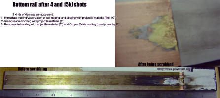
The heat of the
discharge was so intense that it blasted everything at the moment the
pulse took place. After the pulse was over molten aluminum bonded and
distributed itself along the rails. Finally copper oxide coated
everything, but came off without much effort. Looks like a simple brush
should be able to clean the entire gun without the need for disassembly. I
may have to mill that blasted pit though. Its color seems to indicate that
the two metals have been alloyed.

10/20/02: Just back
from the Wisconsin Dells Teslathon. Thanks for everyone who showed up!,
and a big thank you for D.C. Cox for hosting this fantastic event! It was
well worth the 14 hour drive! Showing the Rail Gun to the public was quite
an experience: My project generated a lot of interest and I found myself
explaining over and over again its principle of operation to countless
interested High Voltage enthusiasts. I also got to discuss the more
technical parts of the project with some of the highly knowledgeable
people there, which gave me several new and interesting ideas to try.
3 shots in total were attempted at the event, all of them from a distance
of about 6 feet into a projectile stop which consisted of 2 sheets of wood
and 3 sheets of 1" thick high density foam to prevent ricochet. The first
shot was at 150PSI air, no energy on the capacitor bank. The projectile
penetrated the first foam sheet and got stuck there.
 The
second short was at 4kJ and produced some interesting sparks. It
penetrated all 3 sheets of foam. Since everything seemed to be going well
I attempted a last shot with 15kJ, which produced a spectacular shower of
sparks that moved towards the target as a whole unit, scorching the foam.
It was surprisingly quiet. The tumbling projectile hit the foam flat and
stopped at the wood, denting it slightly. The
second short was at 4kJ and produced some interesting sparks. It
penetrated all 3 sheets of foam. Since everything seemed to be going well
I attempted a last shot with 15kJ, which produced a spectacular shower of
sparks that moved towards the target as a whole unit, scorching the foam.
It was surprisingly quiet. The tumbling projectile hit the foam flat and
stopped at the wood, denting it slightly.


Even at very high powers the gun still fired at subsonic velocities.
Looking at the video and projectile it becomes obvious that the greatest
part of the energy delivered at the shots was spent transforming the
armature and rails into a plasma, but this only occurred at the tip of the
projectile: The muzzle velocity for a 150PSI shot from the injector is
somewhere around 100meters per second. At that velocity, a pulse length of
100uS will only apply power to the projectile during its first 1cm travel
on the rails: I.E. Before the projectile had even fully entered the gun
the pulse was already over; since the magnetic field never got behind the
back of the projectile, acceleration was negligible.
Before the gun can be made to work with a metal armature an inductor may
have to be built and added to the circuit so as to slow the pulse down to
the point where the projectile receives power during its entire travel.
Check back Monday for pictures of the rails!
|


