PowerLabs Rail Gun Research Progress!

PowerLabs Rail Gun Research Progress! |
|
|
|
|
|
|
|
|
|
|
Page description: |
|||||||||||||||||||||||||||||||||||||||||||||||||||||||||||||||||||||||||||||||||||||||||||||||||||||||||||||||||||
|
This page carries the images and
videos of the Rail Gun construction effort; a 120-hour endeavor that cost
approximately $800 of my own money, not counting sponsor-supplied materials. All images are high resolution; the original can be seen by
clicking on the thumbnail. This page is no longer being updated. For current information on project status and testing progress please go to the Rail Gun Testing Page. |
|||||||||||||||||||||||||||||||||||||||||||||||||||||||||||||||||||||||||||||||||||||||||||||||||||||||||||||||||||
|
|
|||||||||||||||||||||||||||||||||||||||||||||||||||||||||||||||||||||||||||||||||||||||||||||||||||||||||||||||||||
Day-By-Day Project advances and current project status: |
|||||||||||||||||||||||||||||||||||||||||||||||||||||||||||||||||||||||||||||||||||||||||||||||||||||||||||||||||||
|
10/12/02: Today, exactly one week away from the Wisconsing Dells Teslathon where I hope to present the Rail Gun, the device is COMPLETED and READY TO BE FIRED. The entire gun was disassembled and the rails were thoroughly cleaned with degreaser and pure Isopropyl alcohol. I than milled the first inch and a half of the contact face to be 0.001" lower than the rest of the rails and put Vinyl tape over that. I than experimented with Teflon tape as a means of insulating the other inch of the rails but that did not work (too fragile). I resorted to PFA film for the last inch; it is stronger than Teflon and has the same 500F working temperature. This is a very critical part of the gun; if the projectile scratches or melts this tape it will contact the rails too soon and acceleration will be non optimal. I am currently looking into better ways of ensuring that power is applied only after the projectile has some rail length behind it. Below you will see some pictures of the completed device. Although the gun is ready I still have some optimizations to make; namely installing bleeder resistors across each cap sub bank, installing charging/discharge resistors on the spark gap, and wiring the 24K gold plated HV connectors to the bank. Time to go out and party to celebrate this major stepping stone in my project :) Monday I will test it under power and obtain current waveforms of the discharge.
10/09/02:T-10 and counting. 5 hours today: Finished off the spark gap today and milled one gap for the rail wires. The gun/cap bank combo is heavy enough that I am starting to struggle in getting it on and off the work table and carrying it around the shop so I went off and bought 4 small wheels and bolted them under the capacitor box. Went down to the machine shop, pressure tested the injector to 310PSI, and than fired the gun (just air) at 300PSI multiple times to evaluate what the recoil does with wheels on (it rolls back almost 1cm). Here is what it sounds like at 300PSI: Maximum Power Dry Firing Video. Tomorrow I want to solder the wires in place and thus finish the gun. Still have to buy resistors and install the connectors on it, but I will do those later on. I also have an oscilloscope on order for the lab so I should have circuit discharge waveforms shortly. Aside from machining a few projectiles my work at the machine shop for this gun is almost complete :)
10/07/02: T-12 and counting. I was at the machine shop today from 5PM
to 8:30PM and finished most of the capacitor bank box. Now it has a 2"
wide triangle in each corner where the top will bolt to and a wide
polycarbonate bar across the middle to give it more structural rigidity.
Also cut, machined and drilled the two end terminals. Tomorrow I will
drill, thread and countersink 8 bolt holes through the top and box,
install the spark gap, and than try to make a mount for the gun to couple
to the box top. We'll see. After that all that I just have to solder the
wires into the capacitor terminals, make connections inside the bank,
install the resistors, and it will be DONE!
10/02/02: First test
firings: Machined and drilled the rest of
the capacitor busbars today. Looks like they will need some more work
before I can get everything to fit. Today I wired a push button switch to
the injector valve, connected the tank to a 2600PSI air tank with a
regulator and attempted a few discharges; first a 200PSI dry shot (very
loud, the gun sounds like a pistol) which blew some pieces of wood off the
ground a couple feet ahead of the muzzle. Secondly a 100PSI shot with a
very large and heavy copper projectile, and finally, a 200 PSI shot with
the same projectile, which consisted in a very poorly fitting copper bar
some .25x.55x3". The projectile was very heavy and didn't seal very well
with the barrel, so these shots by no means represent what the injector is
capable of, nor what the gun will ultimately be shooting.
10/01/02: The objective today was
to machine new projectiles for the injector and video a test firing at
high pressures. After hooking up the compressor to the injector tank I
found out that as feared the compressor was destroyed during previous
tests (during which it got up to 220PSI). It now stops at 80PSI due to
(this was revealed during the autopsy) a damaged rubber seal which was due
to excessive heat. 9/30/02: Insulated the gun cables using electrical tape, squared off the gun mount sides and the injector rails at the mill, bolted the injector end plate in place, screwed the tank in (a process which involved taking the injector off the mount and gun) and did a few 100PSI test firings. The gun is now COMPLETE!!!
The finished Device:
Honestly, I think the gun looks better (cleaner, lighter) without that huge air tank next to it, but since this is about functionality more than looks, it'll stay. I am currently investigating the possibility of running a full unregulated Nitrogen gas tank line (that's almost 3000PSI) to the injector through a special valve for supersonic injection velocities, but for now this is what the gun will look like. Tomorrow I hope to finally test fire it at high pressures and video it. 9/28/02: Machine shop is closed today but with no time to waste I shrink wrapped the gun wires in my dorm room. 9/28/02: Bought coaxial connectors and heat shrink tubing at Radio Shack. I will use coax connectors to connect the charger to the capacitor bank, and insulate the rail gun connections with heat shrink. $14. 9/27/02: 7 hours of machine shop work today. First I shortened the two 1/2" polycarbonate sheets that rise the gun from its mount so as to make the gun lower; this will provide less angular momentum at the base and the reduced torque will make it less likely for the gun to break off its mount due to recoil. I than cut 2 square 1/4" thick polycarbonate sheets, glued them to the gun mount risers, glued the risers to the base, drilled 4 holes in each sheet, so now the gun bolts to the mount through them. I noticed one of the rails was slightly behind the muzzle of the gun, so I had to loosen every single bolt, realign them, and than re-tighten all the bolts. I removed the injector, drilled 4 holes in the back, an threaded them to 10 - 24. Also drilled and countersunk 4 holes on the injector back plate. Now all that is left to do is square off the sides of the mounting brackets on the mill, square off the back of the Teflon injector rails, screw the back plate on, screw the tank onto the back plate, insulate the wires coming out of the gun and hook it up to the capacitor bank (not yet completed). This weekend I will insulate the gun wires, and MONDAY it will be COMPLETE and READY TO FIRE! I will try and hydrostatically test the tank to 300PSI and celebrate by testing the injector/gun assembly with compressed air at that pressure (If the compressor collaborates). Everything is looking SOOO good, but I won't post any pictures until the gun is ready now; this page is getting too large.
9/24/02: Some days it is just not my day... Tried drilling 8 holes in each rail to make the connections for the 8AWG oxygen free wires and ended up breaking 2 drill bits. The second one actually EXPLODED and sent drill shrapnel all over the machine shop. All that at a measly 1600RPM (I don't think that's unreasonable at all for copper, even without coolant, and the shavings I was getting didn't seem to be discolored). Ended up spending 3 hours to remove the drill bits and mill slots on the rails as opposed to having 8 separate holes. The rails are all irregular in the ends now. I'll solder the wires on them with high temperature silver solder and than have to mill them again. Hopefully this will all happen tomorrow... If I can make a mount for the gun too that'd make my day, but I probably won't have the time :-/
|
|||||||||||||||||||||||||||||||||||||||||||||||||||||||||||||||||||||||||||||||||||||||||||||||||||||||||||||||||||
|
2 FT |
8735K262 |
|
Teflon Rectangular Bar 1/4" Thick, 1-1/2" Wide, 2' Length |
$14.07 |
$28.14 |
|
|
1 EA |
4738K157 |
|
Brass Solenoid Valve 1/2" NPT Female, 115 VAC |
$54.19 |
$54.19 |
|
|
1 EA |
89675K43 |
|
Alloy 101 Oxygen-Free Copper Sheet .064" Thick, 12" X 24" |
$71.49 |
$71.49 |
|
|
1 EA |
8574K32 |
|
Polycarbonate Sheet 1/2" Thick, 12" X 12", Clear |
$17.05 |
$17.05 |
|
|
Merchandise Total: |
$170.87 |
|||||
 08/09/2002:
At last some real progress! Today with the aid of Rob, our chief
machinist, I had the rail enclosure drilled by the University's CNC
Milling machine. First the entire enclosure was put together, rails,
spacers, and all, and clamped on a large vise. Than the machine was given
the work piece's dimensions and told to mill (a mill bit was used instead
of a drill bit because a relatively large hole was being made along the
fibers of the sides of the enclosure and it was decided that a drill might
force some fibers to split, as opposed to the more gentle "scooping"
action of the milling bit) eight holes starting 0.3500" from the beginning
of the piece and ending 0.3500" from the end, running 0.2400" from the
sides. A 5/16" hardened steel mill bit was used, which matches exactly the
bolts I am using (The mill bit was destroyed in the process of milling the
extremely tough material). Bolt spacing was calculated by the machine
resulting in a perfect distribution of forces on the rail stack. Bolt
alignment was held to 0.0001" accuracy by the machine and the milling of
the entire stack at once ensured that when everything is bolted together
it will fit perfectly.
08/09/2002:
At last some real progress! Today with the aid of Rob, our chief
machinist, I had the rail enclosure drilled by the University's CNC
Milling machine. First the entire enclosure was put together, rails,
spacers, and all, and clamped on a large vise. Than the machine was given
the work piece's dimensions and told to mill (a mill bit was used instead
of a drill bit because a relatively large hole was being made along the
fibers of the sides of the enclosure and it was decided that a drill might
force some fibers to split, as opposed to the more gentle "scooping"
action of the milling bit) eight holes starting 0.3500" from the beginning
of the piece and ending 0.3500" from the end, running 0.2400" from the
sides. A 5/16" hardened steel mill bit was used, which matches exactly the
bolts I am using (The mill bit was destroyed in the process of milling the
extremely tough material). Bolt spacing was calculated by the machine
resulting in a perfect distribution of forces on the rail stack. Bolt
alignment was held to 0.0001" accuracy by the machine and the milling of
the entire stack at once ensured that when everything is bolted together
it will fit perfectly.


 08/08/2002: Today I had the G-9 Garolite
composite cut into the 4 segments that will make up the rail enclosure:
2.2" wide, 0.7" high, and 1' long. The CNC water jet cutter sliced through
the composite which proved itself impossible to cut using a conventional
band saw at a rate of 7 inches per minute and resulted in a perfect cut.
Thanks Marty for letting me use the waterjet for free! Now all I need is
to drill 10 holes (1 hole/inch) through the enclosure and machine contacts
on the rails and the rail stack will be 100% complete!
08/08/2002: Today I had the G-9 Garolite
composite cut into the 4 segments that will make up the rail enclosure:
2.2" wide, 0.7" high, and 1' long. The CNC water jet cutter sliced through
the composite which proved itself impossible to cut using a conventional
band saw at a rate of 7 inches per minute and resulted in a perfect cut.
Thanks Marty for letting me use the waterjet for free! Now all I need is
to drill 10 holes (1 hole/inch) through the enclosure and machine contacts
on the rails and the rail stack will be 100% complete!
 08/02/2002:
After a long delay in obtaining access to the University
CNC water jet
cutter I finally got a hold of the guy who operates the machine and
convinced him to cut my G-9 rail enclosure on the machine. After telling
him about my project he was so interested that he said he would do it for
free (normally there is an hourly charge associated with using the
machine). The machine accepts CAD (Computer Aided Design) input trough a
CAD-CAM (Computer Aided Machining) converter computer to control a nozzle
in 2 dimensions. The ruby nozzle expels a 55000PSI deionized water jet
(produced by a double stroke 50HP intensifier pump with a shock dampner with steel
walls 3" thick!) with a 80grid garnet abrasive to cut absolutely anything with
staggering precision and a smooth finish. The mach 3 hypersonic abrasive jet will
slice through up to 10" of steel in one pass without generating any heat,
and with such ease that the work piece does not even have to be clamped
down. After cutting through the piece the jet is stopped by a dampening
water tank. Thursday I hope to have pictures and perhaps a video of my
work piece being cut. Waterjet cutting was chosen because the inter woven
fiber glass matrix of the material would destroy any saw blade I used, and
also because the CNC cut will make tolerances much tighter, resulting in a
better fitting enclosure.
08/02/2002:
After a long delay in obtaining access to the University
CNC water jet
cutter I finally got a hold of the guy who operates the machine and
convinced him to cut my G-9 rail enclosure on the machine. After telling
him about my project he was so interested that he said he would do it for
free (normally there is an hourly charge associated with using the
machine). The machine accepts CAD (Computer Aided Design) input trough a
CAD-CAM (Computer Aided Machining) converter computer to control a nozzle
in 2 dimensions. The ruby nozzle expels a 55000PSI deionized water jet
(produced by a double stroke 50HP intensifier pump with a shock dampner with steel
walls 3" thick!) with a 80grid garnet abrasive to cut absolutely anything with
staggering precision and a smooth finish. The mach 3 hypersonic abrasive jet will
slice through up to 10" of steel in one pass without generating any heat,
and with such ease that the work piece does not even have to be clamped
down. After cutting through the piece the jet is stopped by a dampening
water tank. Thursday I hope to have pictures and perhaps a video of my
work piece being cut. Waterjet cutting was chosen because the inter woven
fiber glass matrix of the material would destroy any saw blade I used, and
also because the CNC cut will make tolerances much tighter, resulting in a
better fitting enclosure.
 07/18/2002:
After cutting them on the band saw with a guide the rail spacers had some
saw marks on them, and since they will ultimately be in contact with a metal slug
moving at several hundred m/s I decided that having the smoothest surface
possible would be advantageous since it would allow for the lowest
possible friction and thus maximum projectile velocity/minimum parts wear.
I milled a 1/4" wide groove on an aluminium plate, bolted it down, and ran
an 8-segment milling bit at 3600rpm over the virgin grade Teflon rail
spacers at the lowest servo setting on the mill, thus making their
surfaces not only perfectly flat and parallel, but also unbelievably
smooth. Spacers are 0.25" thick and .25" wide, making the final dimensions
of the gun bore 0.2x0.63", or 5x16mm. That's a Today I got a very
interesting comment from a Mercedes Benz engineer who was visiting campus:
He happened to walk into the machine shop right as I was measuring the
rails and he asked me if I was making some kind of busbar... When I
explained my project to him and showed some of the materials I had on the
table for it he said: "WOW, your sponsors don't spare any money, do
they?". I thought it was pretty neat. Just wait until you see the rail
stack, which is hopefully being cut by a CNC waterjet machine tomorrow. :)
07/18/2002:
After cutting them on the band saw with a guide the rail spacers had some
saw marks on them, and since they will ultimately be in contact with a metal slug
moving at several hundred m/s I decided that having the smoothest surface
possible would be advantageous since it would allow for the lowest
possible friction and thus maximum projectile velocity/minimum parts wear.
I milled a 1/4" wide groove on an aluminium plate, bolted it down, and ran
an 8-segment milling bit at 3600rpm over the virgin grade Teflon rail
spacers at the lowest servo setting on the mill, thus making their
surfaces not only perfectly flat and parallel, but also unbelievably
smooth. Spacers are 0.25" thick and .25" wide, making the final dimensions
of the gun bore 0.2x0.63", or 5x16mm. That's a Today I got a very
interesting comment from a Mercedes Benz engineer who was visiting campus:
He happened to walk into the machine shop right as I was measuring the
rails and he asked me if I was making some kind of busbar... When I
explained my project to him and showed some of the materials I had on the
table for it he said: "WOW, your sponsors don't spare any money, do
they?". I thought it was pretty neat. Just wait until you see the rail
stack, which is hopefully being cut by a CNC waterjet machine tomorrow. :)

 07/17/2002:
Removed the round edges from the silver plated copper bars. When I ordered
rectangular silver plated copper bars from Mc Master Carr I didn't expect
them to come with round edges and that would make it very difficult to
hold them in place, so I put them on the servo assisted milling machine
and took off enough material that they now have perfectly flat, smooth,
parallel edges. Rail width is now 1,176".
07/17/2002:
Removed the round edges from the silver plated copper bars. When I ordered
rectangular silver plated copper bars from Mc Master Carr I didn't expect
them to come with round edges and that would make it very difficult to
hold them in place, so I put them on the servo assisted milling machine
and took off enough material that they now have perfectly flat, smooth,
parallel edges. Rail width is now 1,176".


 07/15/2002:
After some time off from work during which I was looking for a suitable
safety gap to protect and remotely drain the capacitor bank I decided to
change the focus of my work away from the power supply and work on the
rails a bit. Today I cut (on the bandsaw) the 3 foot long silver plated
1/4thick copper rail into two individual rails, each one 13.5" long. I
also made a 45 degree taper (on the belt sander) on their ends which will
serve as an arc breaker should any arcing occur at the muzzle. I also cut
(band saw) the virgin grade Teflon rail spacers to 1' length each and
tapered them to 45" (belt sander), and cut all the parts (table saw) for
the slug pneumatic injector. No pictures of the injector yet, but it will
have a barrel length of 25cm, which means that the gun + injector assembly
just fits on top of the capacitor bank. Now looking for a fast solenoid
valve to control the 250PSI burst of compressed gas that will accelerate
the slug for rail injection at hopefully 100m/s+.
07/15/2002:
After some time off from work during which I was looking for a suitable
safety gap to protect and remotely drain the capacitor bank I decided to
change the focus of my work away from the power supply and work on the
rails a bit. Today I cut (on the bandsaw) the 3 foot long silver plated
1/4thick copper rail into two individual rails, each one 13.5" long. I
also made a 45 degree taper (on the belt sander) on their ends which will
serve as an arc breaker should any arcing occur at the muzzle. I also cut
(band saw) the virgin grade Teflon rail spacers to 1' length each and
tapered them to 45" (belt sander), and cut all the parts (table saw) for
the slug pneumatic injector. No pictures of the injector yet, but it will
have a barrel length of 25cm, which means that the gun + injector assembly
just fits on top of the capacitor bank. Now looking for a fast solenoid
valve to control the 250PSI burst of compressed gas that will accelerate
the slug for rail injection at hopefully 100m/s+.


So far I still need to get clearance to use the Lathes, the CNC mill (that takes a long time, given the complexity of the machine), and the welding machines (MIG and Oxy-Acetylene). If I decide to machine the G-9 rail holder I will probably do it here since it will require carbide cutters and drills.

 06/25/2002: Got checked out by the machine shop
supervisor to utilize the non-metals workshop belt/disk sander, spindle
sander, angle grinder, drill press,
table saw, band saw, jigsaw, hand saw, angle saw. Also got some instructions on how
to weld polycarbonate sheets together using 1,2-Chloroethane.
06/25/2002: Got checked out by the machine shop
supervisor to utilize the non-metals workshop belt/disk sander, spindle
sander, angle grinder, drill press,
table saw, band saw, jigsaw, hand saw, angle saw. Also got some instructions on how
to weld polycarbonate sheets together using 1,2-Chloroethane.

 A good deal of the Rail Gun construction will take place on this workshop;
here I can cut/sand/drill/thread all the parts for the capacitor bank
assembly, power supply box, and part of the structural pieces that will
hold the Rail Gun to its capacitor bank. Aside from the rail enclosure
which will be under extreme stress I plan on making all structural parts
from Polycarbonate. I may use something cheaper on the charging supply
since that is not under any sort of mechanical stress.
A good deal of the Rail Gun construction will take place on this workshop;
here I can cut/sand/drill/thread all the parts for the capacitor bank
assembly, power supply box, and part of the structural pieces that will
hold the Rail Gun to its capacitor bank. Aside from the rail enclosure
which will be under extreme stress I plan on making all structural parts
from Polycarbonate. I may use something cheaper on the charging supply
since that is not under any sort of mechanical stress.

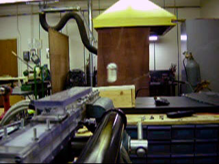
My advisor, Dr. Brad King, made available for me this table on the laboratory, along with storage space for the material I obtained so far. The table sits next to a massive high vacuum chamber where Ion propulsion engines and other forms of advanced space propulsion are tested.

Some of the power supplies available in the laboratory include low and high voltage DC and AC stabilized and current/voltage monitored power rack supplies used to feed the Ion Engines and the vacuum chamber line degassing heaters. I will most probably be building my own capacitor charging supply for the gun however, since I want it to be portable and self contained.
The vacuum chamber by far occupies the most space in the laboratory. It is connected to a very large 2-stage water cooled oil sealed rotary pump which than connects to a very large Liquid Helium cryopump. The entire system is designed to run for days at a time testing ionic and plasma propulsion engines. Although I won't be using it for my project (though I haven't completely ruled out the possibility of hiding inside it when the gun is fired for the first time:) ) it will probably be featured in most of my lab pictures since it pretty much takes up the whole room. I would love to test some of my own plasma propulsion ideas on that chamber some later time, but for now my complete focus is on the RailGun project.


|
1 EA |
88865K312 |
|
Alloy 110 Silver-Plated Copper Rectangle 1/4" Thick, 1-3/8" Width, 3' Length |
$19.10 |
$19.10 |
today |
|
|
1 EA |
8574K85 |
|
Polycarbonate Sheet 1/4" Thick, 48" X 48", Clear |
$90.35 |
$90.35 |
today |
|
|
1 FT |
84955K12 |
|
PFA Film .001" Thick X 24" Wide |
$3.93 |
$3.93 |
today |
|
|
4 FT |
8735K25 |
|
Teflon Rectangular Bar 1/4" Thick, 1" Wide |
$9.41 |
$37.64 |
today |
|
|
1 EA |
8661K127 |
|
Grade G-9 Garolite Sheet 1/2" Thick, 12" X 12", Gray-Brown |
$54.81 |
$54.81 |
today |
|
|
1 PK |
91286A196 |
|
Ultra-Coated Grade 8 Hex Head Cap Screw 5/16"-24 Thread, 2-1/2" Lg |
$5.96 |
$5.96 |
today |
|
|
25 EA |
93915A140 |
|
High-Pressure Self-Sealing Locknut 5/16"-24 Screw Sz, Fine Thread, 9/16" WD, 17/64" HT |
$3.40 |
$85.00 |
today |
|
|
1 PK |
98180A120 |
|
Ultra Coated High Strength Steel Washer 5/16" Screw Size, 11/32" ID, 11/16" OD,.051" Min Thick |
$2.60 |
$2.60 |
today |
|
|
10 EA |
91740A104 |
|
Thread Restoring Bolt 1/4"-20 Coarse Thread X 1-1/4" Long |
$3.47 |
$34.70 |
today |
|
|
Merchandise Total: |
$334.09 |
|
|||||
I ended up paying $394 with the shipping. These will allow me to make the capacitor box (48x48" polycarbonate sheet) and the rail enclosure (G-9 Garolite, Teflon spacer, PFA insulator, bolts, nuts, washers, etc), The rails will be made from the copper rectangle. I still need parts for the power supply; V and A meters, bleeder resistors, discharge switches, high voltage cables, inverter, etc... Anyone have any of this stuff?
|
|
Testing: |
|
All videos are .MPG format. For
powered testing videos go to the Rail Gun
Testing Page.
195PSI air
tank/valve/reducer test video (1.2mB; a blast of air blows a
wooden block across the room). |
|
|
|
Comments? Mail me. Last updated 11/02/10 |
|
Copyright
� 2002 by Sam Barros. All rights reserved. Removing any material from this site for display without consent from its author consists in an infringement of international copyright laws and can result in fines up to $50000 per infringement, plus legal costs. So ASK ME before you remove anything from here. |